This post summarizes the internal architecture of Kubernetes (k8s). For my previous post on user-facing aspects, see Part 1 of the series.
- An architectural style that is followed throughout the control plane of k8s is of components communicating with each other using a data store (etcd) as the intermediary. Updates made to etcd are picked up by relevant observers and acted upon (see figure below).
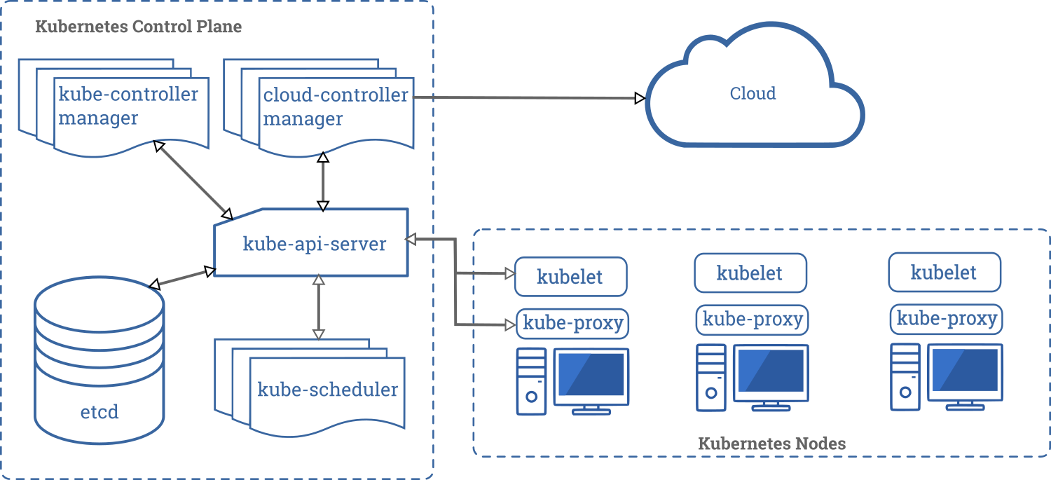
- k8s has master and worker nodes.
- The master node manages the overall cluster and runs these processes: etcd, API server, Scheduler and a Controller Manager.
- Worker nodes execute the tasks, and they run: kubelet, kube-proxy and the container runtime (say Docker).
- etcd is a distributed KV store built on Raft, and provides an hierarchical key namespace (/registry, /registry/pods etc). The values for keys are a JSON representation of the corresponding resource.
- All cluster state is stored in etcd. Only API Server talks to etcd directly. If you run multiple instances of API Server, they lock etcd using optimistic locking.
- API Server also authenticates and authorizes requests. It has a well developed plugin mechanism to customize these, and even additional modifications to the requests if needed.
- The Scheduler is likewise highly customizable in terms of the scheduling policy it will use to choose nodes where pods can be run. You can even run multiple schedulers that handle different subsets of pods!
- The ControllerManager manages the many resource specific Controllers (DeploymentController, JobController, StatefulSetController etc). Each Controller watches for etcd changes of its interest in order to decide what to execute. Each Controller more-or-less operates independently. Controllers may invoke the Scheduler or Kubelet indirectly, by posting appropriate updates to etcd via API Server.
- kubelet is the process on a worker node that actually starts and stops pods and checks on their health. It polls API Server to decide what to do.
- kube-proxy used to proxy traffic to pods, but now only sets up iptables rules for pod related load balancing.
- Apart from the app specific containers for a pod, a system container is also launched that creates the necessary network namespaces that all the app specific containers will share. k8s needs pods to be able to communicate with each other based on their actual IPs. Hence, traffic between pods can’t be NAT-ted (IPs need to be preserved).
- kube-proxies listen for new Services to come online and then update iptables to point to them.
- The control plane can be scaled up by running fallback instances of each component. A leader election algorithm ensures only one component is active at any time.
- Apart from providing desired CPU and memory, k8s nodes can be enhanced with custom resource types (eg: GPUs) that are specific to your needs. Custom resources should be sized in integer quantities.
- Containerized apps can still see the node’s total CPU and mem resources unless they use specialized approaches to figure out their actual limits. k8s has sophisticated mechanisms for resource usage monitoring, allocation and metrics.
- k8s classifies pods into 3 QoS classes for prioritization in case of a resource crunch. Pods are Guaranteed if their initial request of CPU and mem resources is equal to their desired upper limit and Burstable if not. If limits are not mentioned at all, the pod is BestEffort.
Are there QoS classes for moving packets between pods and the outside world?
Nothing as simple as a QoS class yet, but the bleeding edge of k8s has networking plugins that can use standard Linux tools to do traffic shaping – https://kubernetes.io/docs/concepts/extend-kubernetes/compute-storage-net/network-plugins/#support-traffic-shaping
Here’s a full list of networking plugins that you can try out in k8s – https://kubernetes.io/docs/concepts/cluster-administration/addons/#networking-and-network-policy